Overview
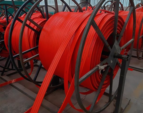
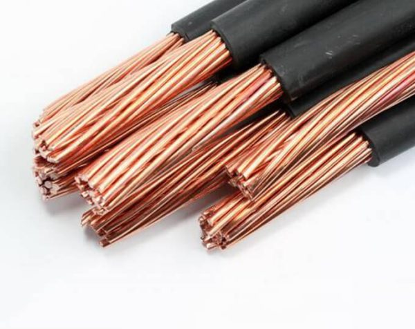
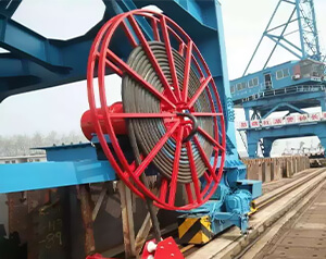
Cable reels, also frequently called cable drums, are essential devices used for the managed winding and unwinding of power and signal cables. They are critical components in heavy industries, manufacturing, construction, and port operations. The specific application and performance of a cable reel depend heavily on its drive mechanism and the materials being wound.
Core Working Principles: Types of Cable Reel Drive Mechanisms
The operational principle of a cable reel is defined by how it is powered. Below are the four most common drive forms applied in industrial settings:
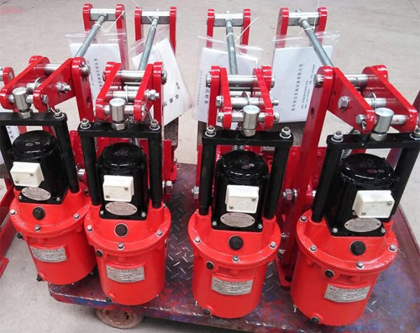
1. Spring-Driven Reels
Similar to a standard tape measure, these utilize a spiral spring for power.
- How it works: When the cable is pulled out, the spring tightens, storing energy. When the external force is removed, the spring releases its energy to automatically retract the cable.
- Best for: Shorter distances and lighter cable loads.
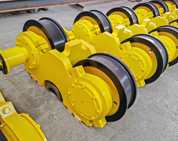
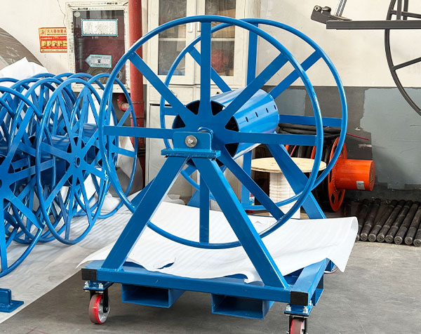
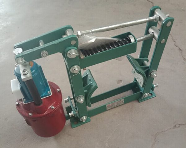
2. Counterweight (Deadweight) Reels
This mechanical device uses gravitational potential energy to manage the cable.
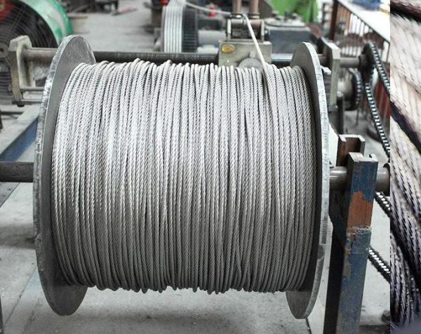
- How it works: Pulling the cable out rotates the reel and lifts a heavy weight via a connected steel wire drum (storing energy). When retraction is needed, the weight descends, releasing energy to rotate the drum and wind the cable synchronously.
- Best for: Applications requiring very constant tension, often found in older or extremely heavy-duty systems.
3. Magnetic Coupling Reels
This type uses a permanent magnetic coupler as a differential adjustment mechanism to output constant torque.
- Retraction: When the equipment moves towards the anchor point, power drives the reel through the coupler to wind the cable. The torque is adjustable to synchronize winding speed with travel speed.
- Extension: When moving away, a one-way clutch disengages the drive power. The movement of the equipment drags the cable out, overcoming the system resistance (hysteresis) to release the cable smoothly.
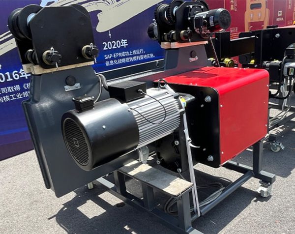
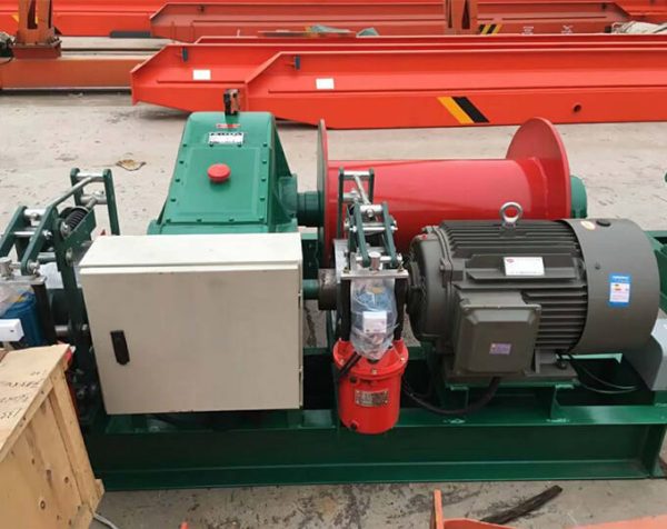
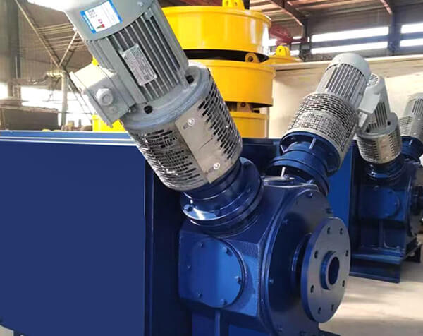
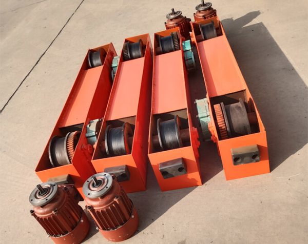
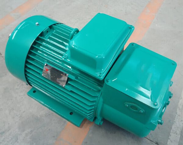
4. Torque Motor Reels
These utilize the unique mechanical characteristics of torque motors: high torque at low speeds, and low torque at high speeds.
Best for: Long-distance, high-speed, and heavy-cable applications requiring precise tension control.
How it works: This characteristic perfectly matches cable reeling requirements. As the winding diameter increases (and speed needs to decrease), the motor automatically adjusts to maintain constant tension and synchronization with the mobile equipment.
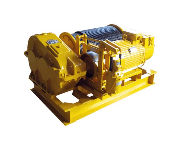
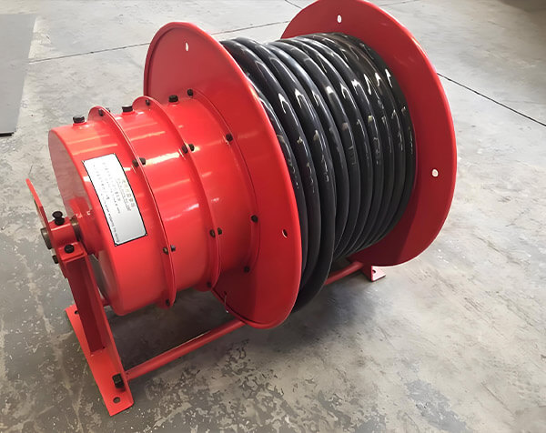
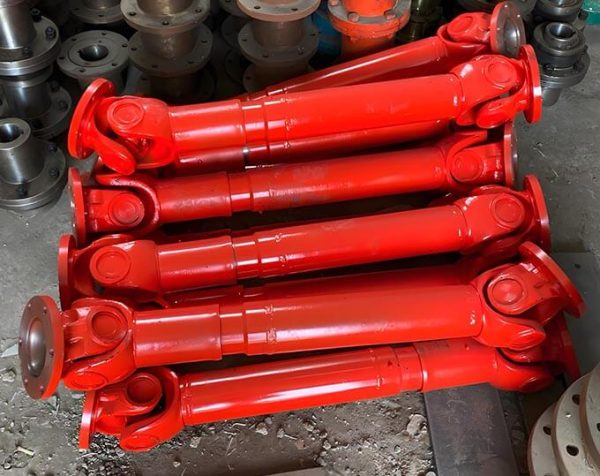
The Anatomy of a Cable Reel: Internal Structure
While designs vary based on the drive type, most industrial cable reels share a fundamental internal structure comprised of these key parts:
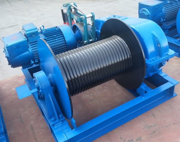
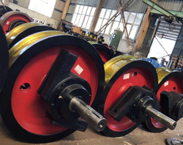
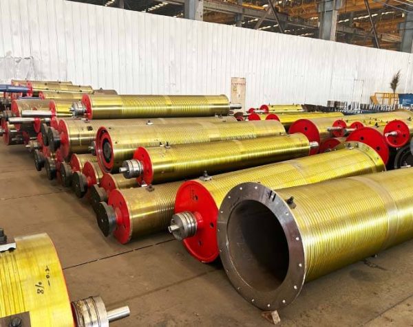
- The Winding Drum : The core component where the cable is stored. Its diameter and shape are critical to ensure the cable does not bend below its minimum radius.
- Drive Mechanism : The "engine" of the reel (as described above), controlling movement either via springs or motors to improve efficiency and reduce cable wear.
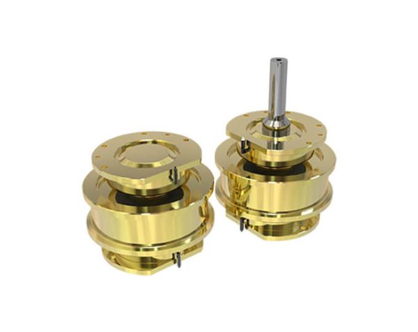
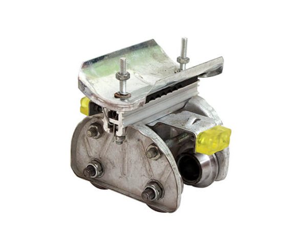
- Conductive Slip Ring Box : (Crucial Component) Located internally, this transfers electrical power from a stationary source to the rotating cable drum. It houses the slip ring and brush assembly.
- Support Frame : The main structure holding the drum, connecting it rotatably to the equipment base. It often includes guides to ensure tidy cable spooling.
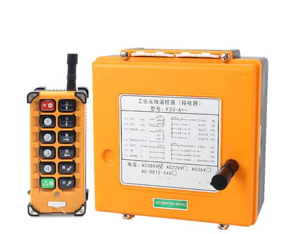
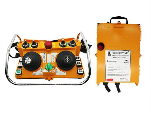
- Automatic Control System : Advanced modern reels integrate sensors (like RFID or encoders) to automate retraction/extension, enhancing safety and efficiency.
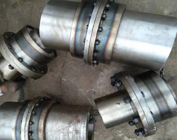
The Critical Function of the Conductive Slip Ring
Without a slip ring, an industrial cable reel would be useless for transferring power while rotating, as the cable would quickly twist and break.
How Slip Rings Prevent Cable Twisting
The conductive slip ring assembly inside the reel consists of two main parts:
- The Rotor : Connected to the rotating drum and carries the input/output wires of the moving cable. It rotates at any angle along with the equipment.
- The Stator : Remains relatively stationary and is connected to the fixed power source.
The Function: Brushes on the stator maintain constant contact with the rings on the rotor. This design allows for the continuous transmission of current and signals from a fixed point to a rotating point while the equipment is turning. This effectively prevents the cable from twisting, tangling, or snapping during operation.


-600x476.jpg)