


Gantry Crane
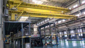
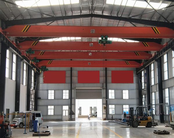
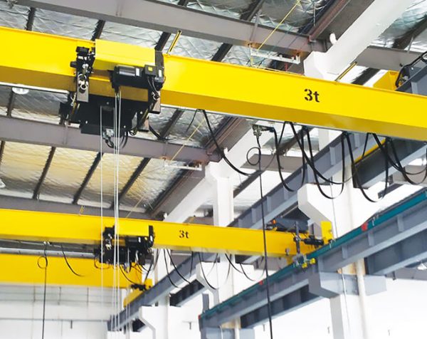
Overhead Crane
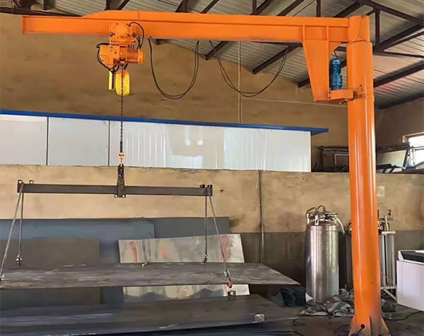
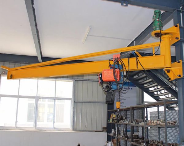
Slewing Jib Crane
Lifting Electromagnet
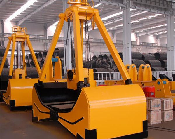
Electric Grab
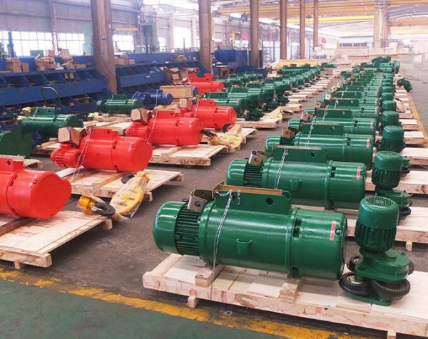
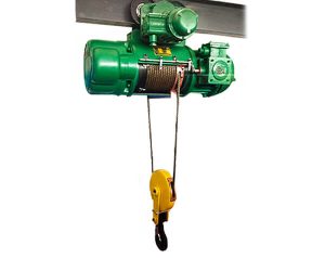
Electric Hoist
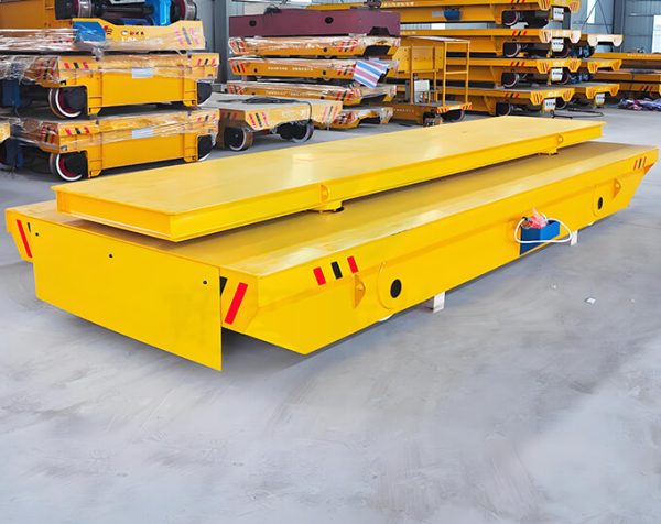
Electric Transfer Cart
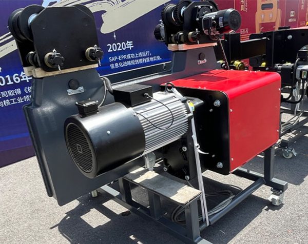
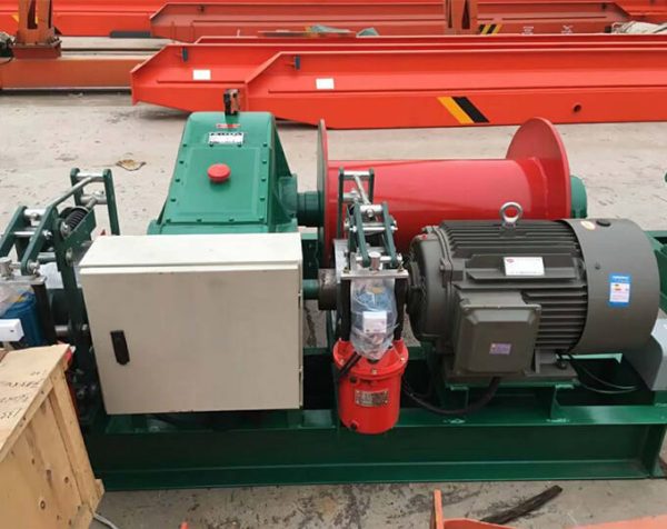
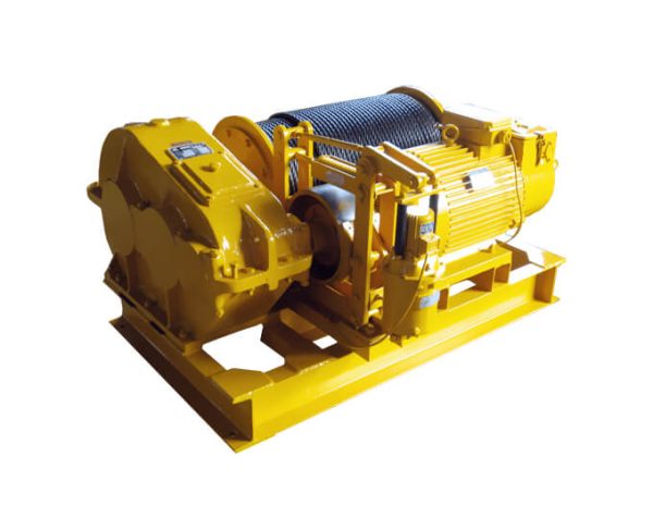
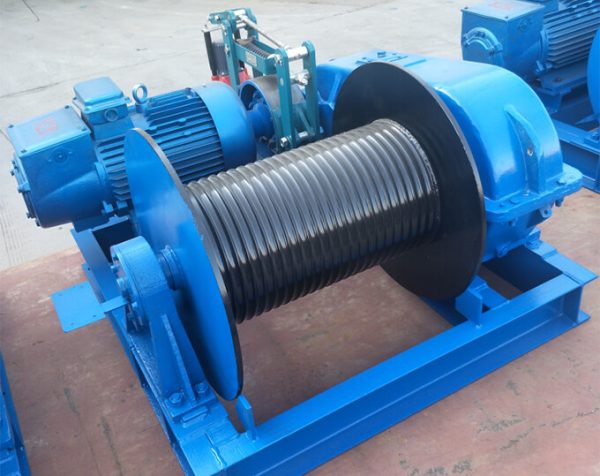
Winch
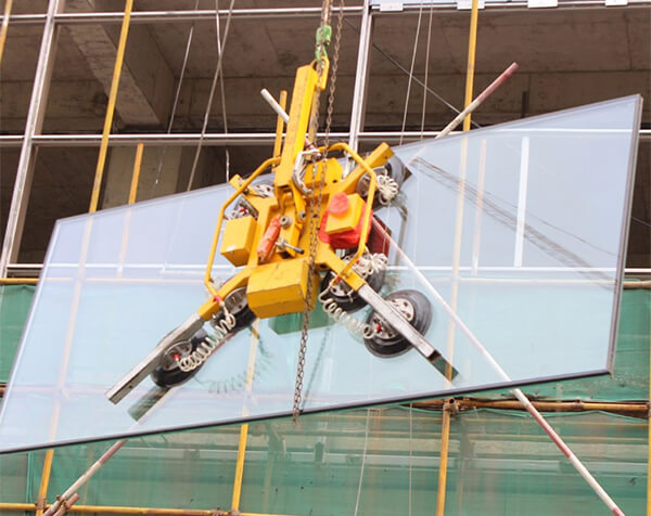
Vacuum Lifter
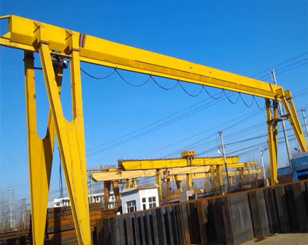
MH Type Electric Hoist Gantry Crane

Single Beam Tire Gantry Crane
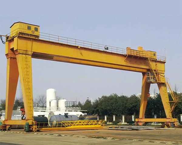
50~100t Winch Gantry Crane
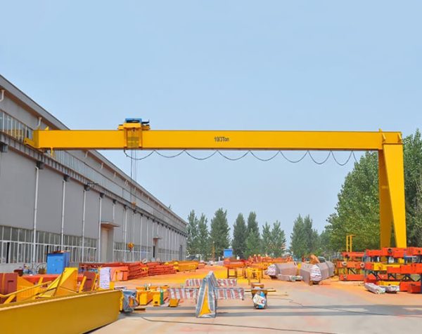
L Type Electric Hoist Gantry Crane
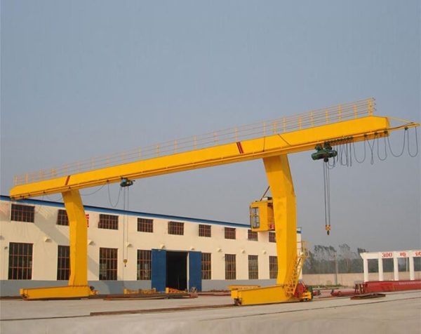
BMH Type Semi Gantry Crane
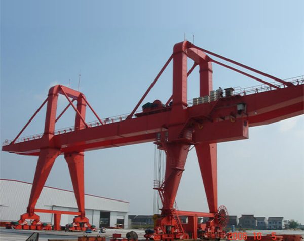
A Type Double-beam Hook Gantry Crane
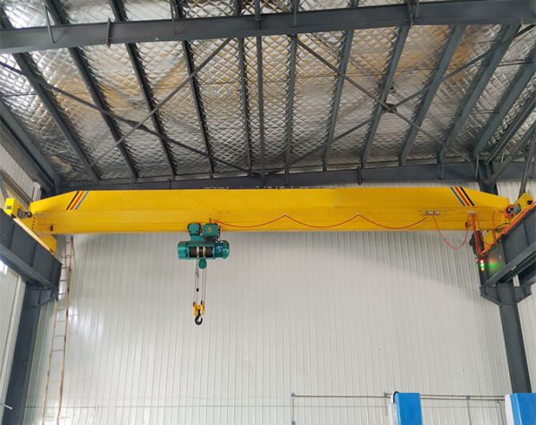
LDA Type Electric Single Beam Crane
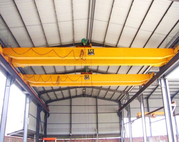
LH Type Electric Hoist Bridge Crane
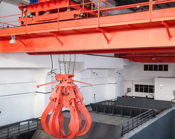
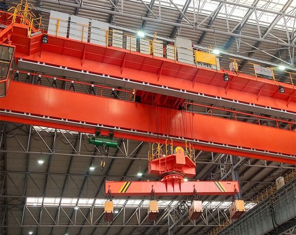
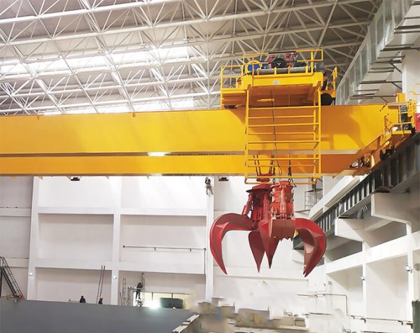
Double Beam Multilobe Grab Bridge Crane
LB Type Explosion Proof Electric Girder Crane
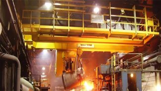
QC Type Electromagnet Bridge Crane
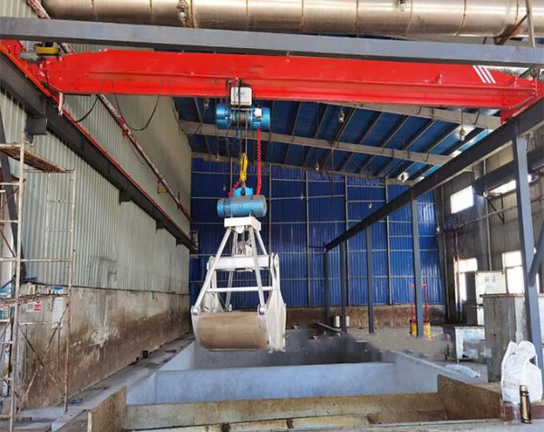
LDZ Type Single Beam Grab Crane
-600x476.jpg)
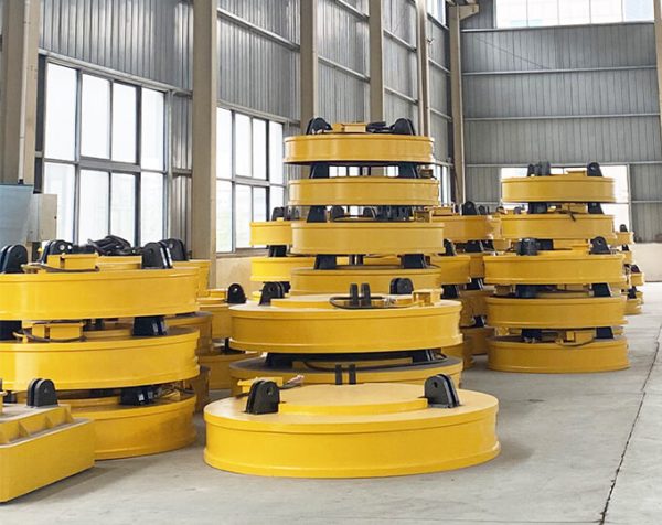
MW5 Scrap Lifting Electromagnet
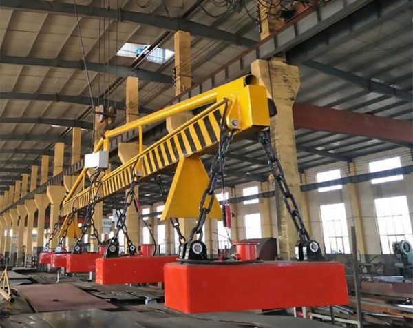
MW22 Lifting Electromagnet for Billet, Girder Billet and Slab
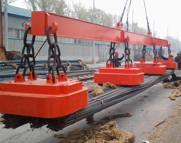
MW38 Lifting Electromagnet for Bundled Rebar and Profiled Steel
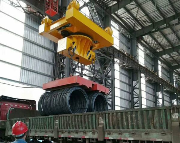
Lifting Magnet for Speed Wire(Coiled Bar)

Lifting Electromagnet For Lifting and Transporting Steel
Hydraulic Magnet Lift
Four Rope Steel Wire Rope Grab
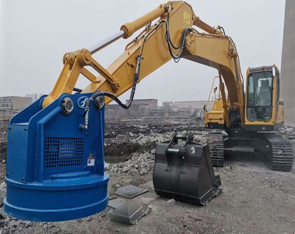
Excavator Grab Bucket
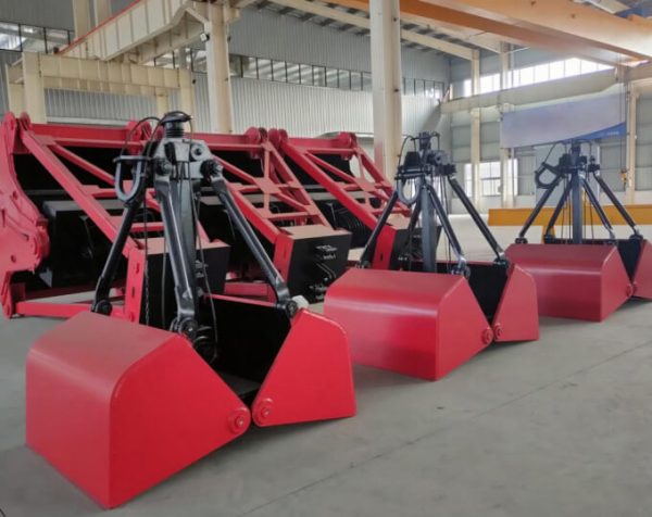
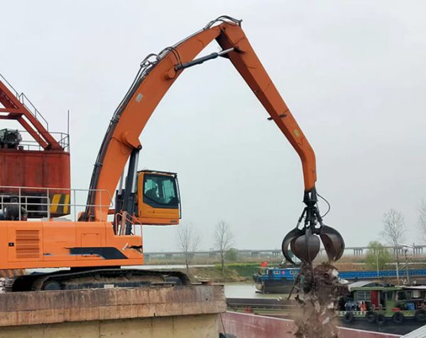
Hydraulic Muti-flap Grab
Single Rope Hanging Grab
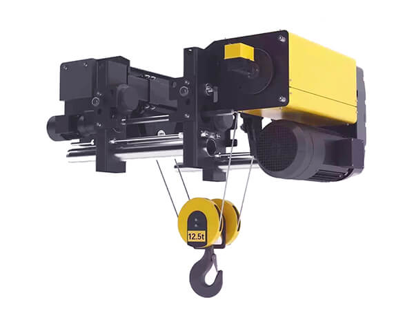
European Double Beam Wire Rope Hoist
European Explosion Proof Hoist
European Wire Rope Electric Hoist
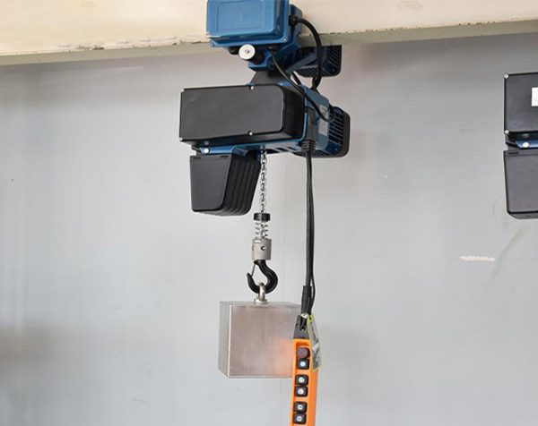
European Chain Hoist
Metallurgical Electric Hoist
HB Type Explosion Proof Electric Hoist
Electric Transfer Cart
360°Turn Trackless Electric Transfer Cart
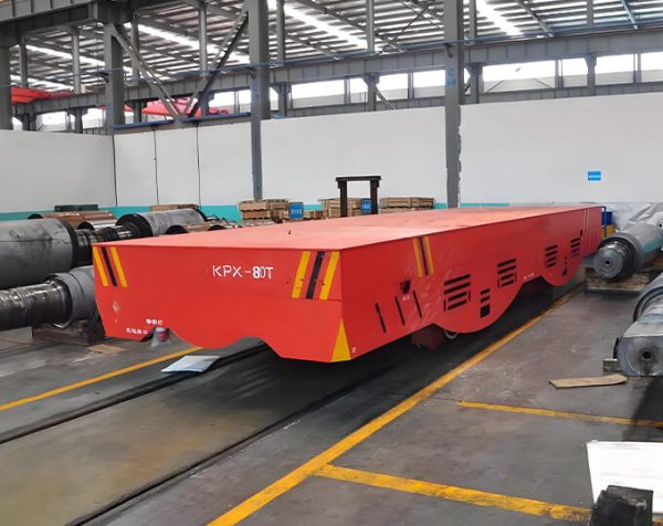
KPX Battery Powered Electric Flat Carts
KPJ Cable Powered Electric Flat Carts
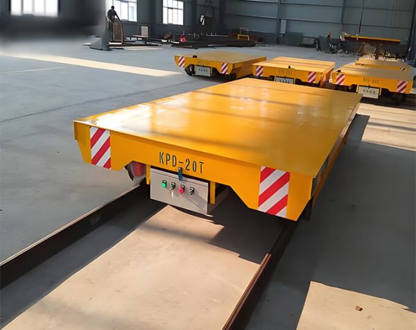
KPD Rail Powered Electric Flat Carts
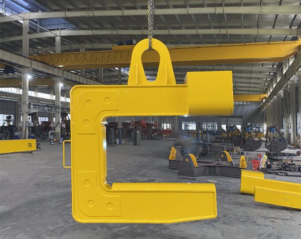
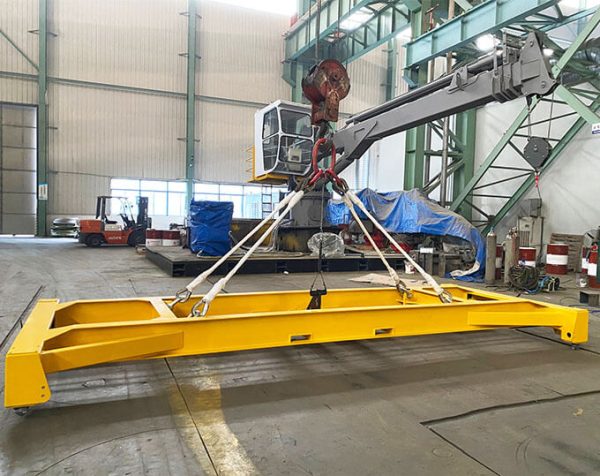
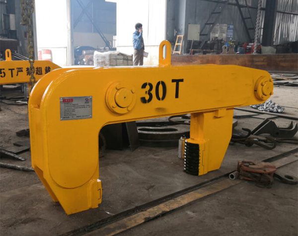
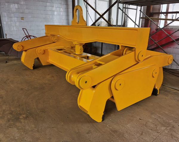
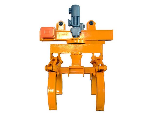
Lifting Spreader
Lifting Clamp
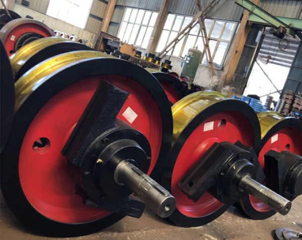
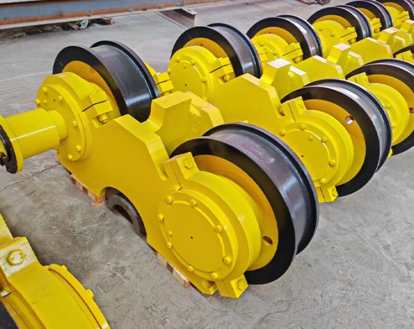
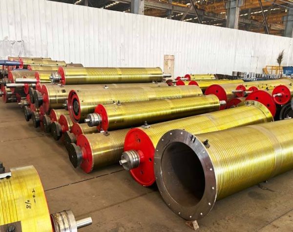
Crane Wheel
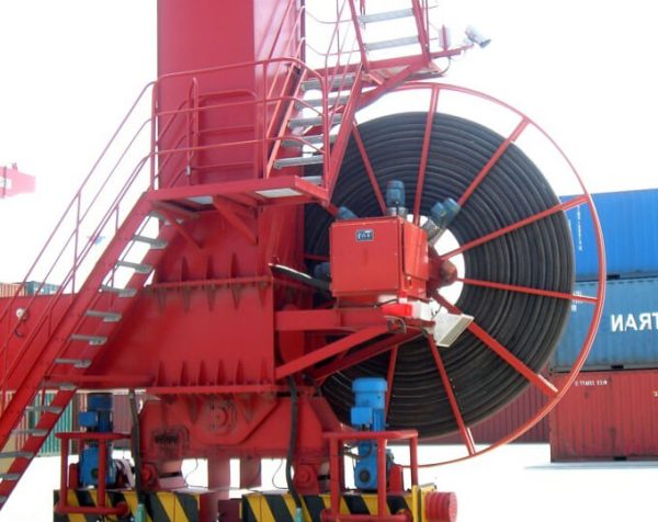
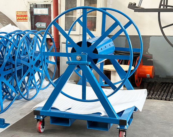
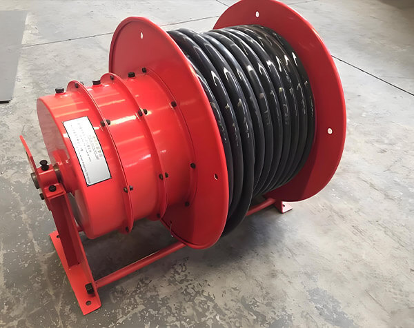
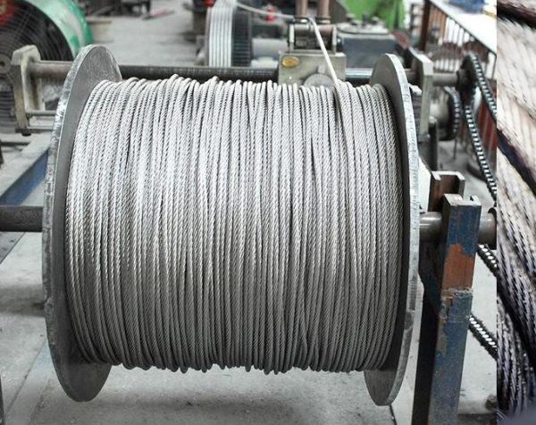
Cable Reel
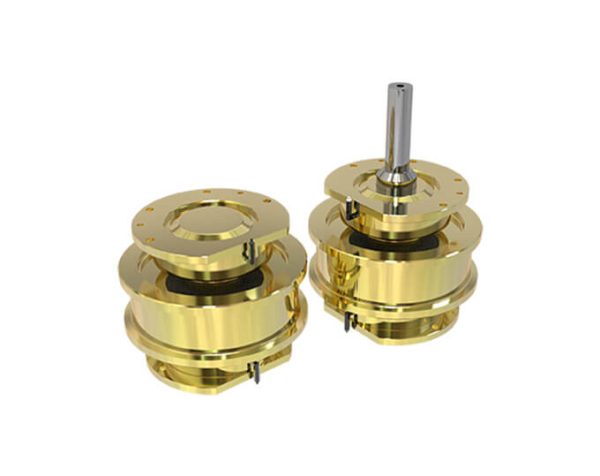
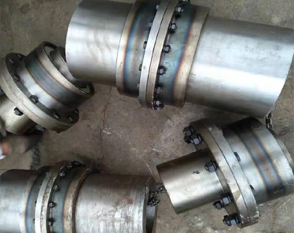
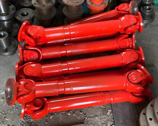
Coupling
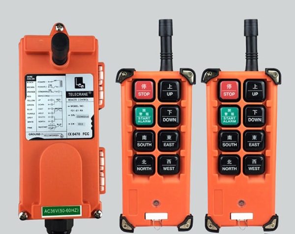
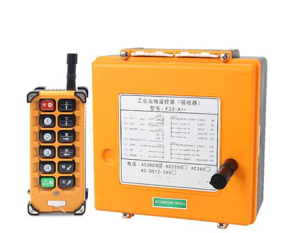
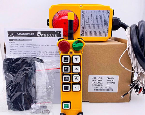
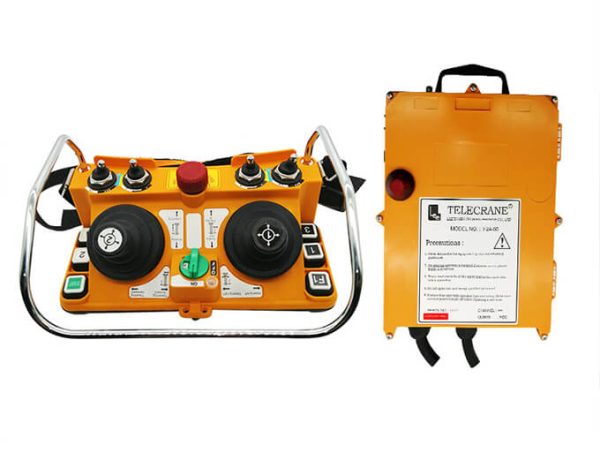
Remote Controller
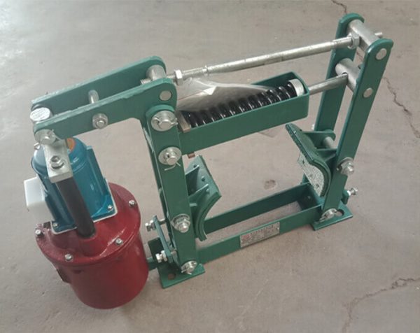
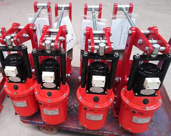
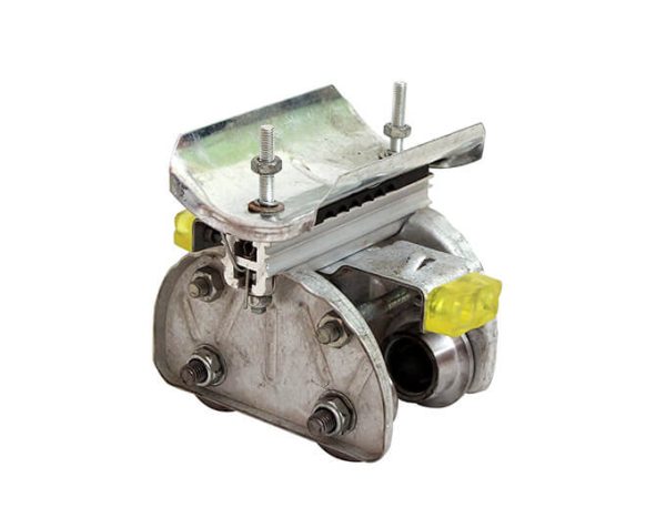
Brake
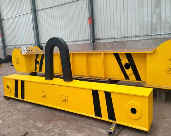
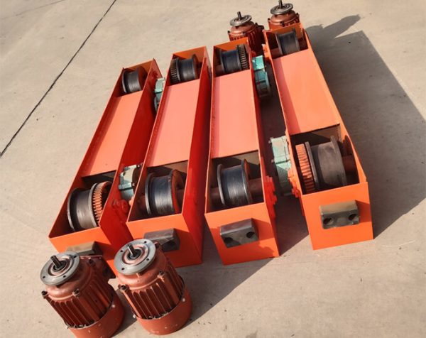
Overhead Crane End Beam
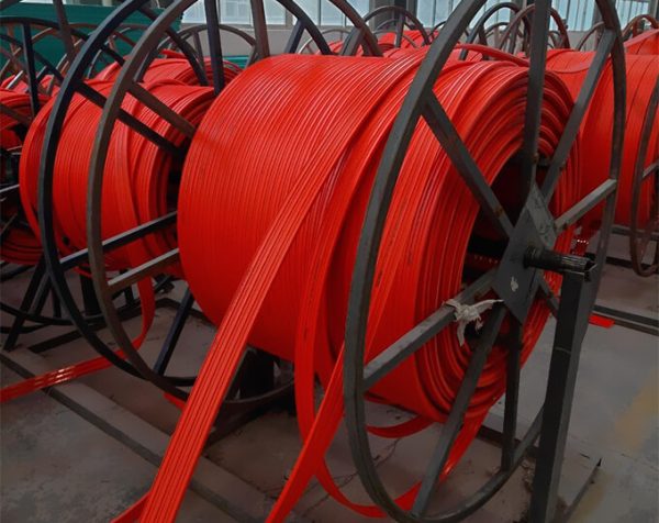
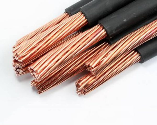
Electric Power Line
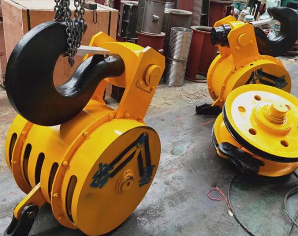
Other Parts